ATA 21: Air Conditioning - Ventilation - Pressurisation - Pneumatics Flashcards
(88 cards)
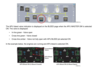
- With engines and APU running and APU bleed valve selected ON, the engine bleed valves:
(a) Open, X BLEED valve opens, APU bleed valve closes
(b) Close, X BLEED valve opens, APU bleed valve opens
(c) Close, X BLEED valve closes, APU bleed valve opens
(b) Close, X BLEED valve opens, APU bleed valve opens
With the PACK FLOW selector switch in NORM, opening of the APU bleed valve will
cause both the flow control valves to regulate in the:
(a) High flow mode
(b) Low flow mode
(c) Normal flow mode
(a) High flow mode
The amber FAULT light illuminates in the HOT AIR push button switch as a result:
(a) The hot air and trim valves run close
(b) Both pack valves close
(c) The turbine by-pass valve runs close
(a) The hot air and trim valves run close
Which of the following computers controls the cabin and cockpit conditioned air?
(a) One zone controller that passes information and instructions to two pack controllers for four zones
(b) Three zone controllers that pass information and instructions to two pack controllers for four zones
(c) Two pack controllers that pass information and requests to three zone controllers
(a) One zone controller that passes information and instructions to two pack controllers for four zones
When a temperature selector rotary knob is adjusted:
(a) Its associated trim air valve always moves to a different position
(b) No relationship exists between a temperature selector knob and the trim air valve
(c) A signal is sent to the zone controller requesting a different temperature and adjusts trim air valves accordingly
(c) A signal is sent to the zone controller requesting a different temperature and adjusts trim air valves accordingly
Pressurization indications may be found on which ECAM page/s:
(a) The in-flight ECAM cruise page, the cab press page and the door/oxy page
(b) Only on the cab press page
(c) Only on the bleed page
(a) The in-flight ECAM cruise page, the cab press page and the door/oxy page
The Ram Air Inlet valve is controlled…
(a) Automatically by the pack controller
(b) By the RAM AIR pushbutton
(c) By the Ditching pushbutton
(a) Automatically by the pack controller
Pressurization indications may be found on which ECAM page/s:
(a) The in-flight ECAM cruise page, the cab press page and the door/oxy page
(b) Only on the cab press page
(c) Only on the bleed page
(a) The in-flight ECAM cruise page, the cab press page and the door/oxy page
To change to the maximum descent cabin rate of 400 feet per minute you would….
(a) Go to the DES page and enter -400 in the DES CABIN RATE field
(b) Select it manually on the overhead panel
(c) Enter 400 in the DES CABIN RATE field on the CRZ page
(c) Enter 400 in the DES CABIN RATE field on the CRZ page
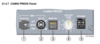
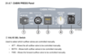
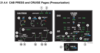
AIR_1
Understand the control functions and indications on the AIR panel.
1. RAM AIR pb
Selected ON (guard lifted) - The ram air inlet opens if differential pressure is less than ____ psi and the _______ pb is not selected ON.
VOL. II, 21.4.5

AIR_1
Understand the control functions and indications on the AIR panel.
1. RAM AIR pb
Selected ON (guard lifted) - The ram air inlet opens if differential pressure is less than 1.0 psi and the DITCHING pb is not selected ON.
VOL. II, 21.4.5

AIR_1
Understand the control functions and indications on the AIR panel.
2. PACK 1(2) pbs
- On (lights out) - The respective pack operates _________.
- Selected OFF - The respective pack flow control valve ______.
- FAULT - Illuminates amber if the valve position ________ with the selected position or if a pack _____ occurs.
- The respective pack flow control valve closes _________.
- It does not illuminate when the valve _______ under normal conditions (e.g., engine start).
VOL. II, 21.4.5

AIR_1
Understand the control functions and indications on the AIR panel.
2. PACK 1(2) pbs
- On (lights out) - The respective pack operates normally.
- Selected OFF - The respective pack flow control valve closes.
- FAULT - Illuminates amber if the valve position disagrees with the selected position or if a pack fault occurs.
- The respective pack flow control valve closes automatically.
- It does not illuminate when the valve closes under normal conditions (e.g., engine start).
VOL. II, 21.4.5

AIR_1
Understand the control functions and indications on the AIR panel.
3. PACK FLOW Selector
- Used to exercise _______ control over pack _______ by requesting the desired flow via the _______ controller.
- Regardless of switch position, the zone controller commands high flow when the _______ is supplying bleed air or only one _______ is operating.
VOL. II, 21.4.5
AIR_1
Understand the control functions and indications on the AIR panel.
3. PACK FLOW Selector
- Used to exercise limited control over pack flow by requesting the desired flow via the zone controller.
- Regardless of switch position, the zone controller commands high flow when the APU is supplying bleed air or only one pack is operating.
VOL. II, 21.4.5

AIR_1
Understand the control functions and indications on the AIR panel.
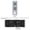
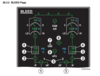
4. COCKPIT and CABIN Temperature Selectors
- Used to select the desired temperature in each ____.
- The positions of the temperature selectors on the AIR panel correspond with the following temperatures:
- COLD - [____°F]
- 12 o’clock - [____°F]
- HOT - [____°F]
Note: The cabin temp selector sets a reference temperature from which individual cabin zone temperatures are adjusted on the forward attendant’s panel.
VOL. II, 21.4.5

AIR_1
Understand the control functions and indications on the AIR panel.
4. COCKPIT and CABIN Temperature Selectors
- Used to select the desired temperature in each zone.
- The positions of the temperature selectors on the AIR panel correspond with the following temperatures:
- COLD - [64°F]
- 12 o’clock - [76°F]
- HOT - [86°F]
Note: The cabin temp selector sets a reference temperature from which individual cabin zone temperatures are adjusted on the forward attendant’s panel.
VOL. II, 21.4.5

AIR_1
Understand the control functions and indications on the AIR panel.
5. HOT AIR 1(2) Pbs
- On (lights out) - The hot air valves operate _______.
- OFF - The respective hot air valve _______.
- FAULT - Illuminates amber if the duct temperature _______ predetermined temperature.
- The respective _______ air valve closes.
- The FAULT light _______ if the pb is selected OFF and the _______ condition no longer exists.
VOL. II, 21.4.5

AIR_1
Understand the control functions and indications on the AIR panel.
5. HOT AIR 1(2) Pbs
- On (lights out) - The hot air valves operate normally.
- OFF - The respective hot air valve closes.
- FAULT - Illuminates amber if the duct temperature exceeds predetermined temperature.
- The respective hot air valve closes.
- The FAULT light extinguishes if the pb is selected OFF and the overheat condition no longer exists.
VOL. II, 21.4.5

AIR_1
Understand the control functions and indications on the AIR panel.
6. ENG 1(2) Bleed Pbs
- On (lights out) - The respective engine bleed valve operates _______.
- OFF - The engine bleed valve and _______ valve _______.
- FAULT - Illuminates amber if any of the following occur:
- The bleed valve is not _______ during engine start or when the _______ bleed valve is open.
- An _______ is detected.
- An _______ is detected.
- A _______ leak is detected.
- The FAULT light _______ when the pb is selected OFF, provided the _______ condition no longer exists.
VOL. II, 21.4.5

AIR_1
Understand the control functions and indications on the AIR panel.
6. ENG 1(2) Bleed Pbs
- On (lights out) - The respective engine bleed valve operates normally.
- OFF - The engine bleed valve and HP valve close.
- FAULT - Illuminates amber if any of the following occur:
- The bleed valve is not closed during engine start or when the APU bleed valve is open.
- An overpressure is detected.
- An overheat is detected.
- A bleed leak is detected.
- The FAULT light extinguishes when the pb is selected OFF, provided the failure condition no longer exists.
VOL. II, 21.4.5
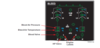
AIR_1
Understand the control functions and indications on the AIR panel.
7. APU Bleed Pb
ON -
- The engine bleed and HP valves ________.
- The crossbleed valve ________ if the crossbleed selector is in the ________ position.
- The air conditioning packs go to ________ flow.
- The APU Bleed valve opens if:
- APU N speed is greater than [_______%_],
- altitude is less than _______ ft_. (climbing) or _______ft_. (descending),
- and no leak is detected in the ________ or ________ side of the bleed system.
- APU N speed is greater than [_______%_],
Off (lights out) - The APU bleed valve ________.
FAULT - Illuminates amber if an APU bleed ________ is detected. The bleed valve closes ______________.
VOL. II, 21.4.5

AIR_1
Understand the control functions and indications on the AIR panel.
7. APU Bleed Pb
ON -
- The engine bleed and HP valves close.
- The crossbleed valve opens if the crossbleed selector is in the AUTO position.
- The air conditioning packs go to high flow.
- The APU Bleed valve opens if:
- APU N speed is greater than [95%],
- altitude is less than 25,000 ft. (climbing) or 23,000 ft. (descending),
- and no leak is detected in the APU or left side of the bleed system.
- APU N speed is greater than [95%],
Off (lights out) - The APU bleed valve closes.
FAULT - Illuminates amber if an APU bleed leak is detected. The bleed valve closes automatically.
VOL. II, 21.4.5

AIR_1
Understand the control functions and indications on the AIR panel.
8. Crossbleed Selector
- AUTO - The valve is normally _______ and _______ if the APU bleed valve is open.
- The crossbleed valve opens after a [_______] second delay.
- The valve _________ automatically if either BMC (Bleed Monitoring Computer) detects a bleed _______, unless an engine start is in progress.
- OPEN - _______ the automatic operation of the valve and manually _______ the valve.
- CLOSE - _______ the automatic operation of the valve and manually _______ the valve.
VOL. II, 21.4.5

AIR_1
Understand the control functions and indications on the AIR panel.
8. Crossbleed Selector
- AUTO - The valve is normally closed and opens if the APU bleed valve is open.
- The crossbleed valve opens after a [10] second delay.
- The valve closes automatically if either BMC detects a bleed leak, unless an engine start is in progress.
- OPEN - Overrides the automatic operation of the valve and manually opens the valve.
- CLOSE - Overrides the automatic operation of the valve and manually closes the valve.
VOL. II, 21.4.5
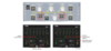
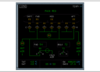
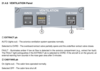
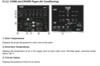
AIR_3
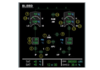
Discuss normal and abnormal indications on the ECAM COND page.
1. Zone Temperatures
Displays the ________ temperature in each zone of the cabin.
V2 21.4.3

AIR_3
Discuss normal and abnormal indications on the ECAM COND page.
1. Zone Temperatures
Displays the actual temperature in each zone of the cabin.
V2 21.4.3

AIR_3
Discuss normal and abnormal indications on the ECAM COND page.
2. Zone Duct Temperatures
Displays the temperature of air in the ________ duct for each cabin zone.
Normally green, becomes amber above __________ temperature.
V2 21.4.3

AIR_3
Discuss normal and abnormal indications on the ECAM COND page.
2. Zone Duct Temperatures
Displays the temperature of air in the supply duct for each cabin zone.
Normally green, becomes amber above predetermined temperature.
V2 21.4.3

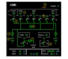
AIR_3
Discuss normal and abnormal indications on the ECAM COND page.
3. Trim Air Valves
Displays the positions of the trim air valves.
• Green - _________
• Amber – Valve ______
V2 21.4.3

AIR_3
Discuss normal and abnormal indications on the ECAM COND page.
3. Trim Air Valves
Displays the positions of the trim air valves.
• Green - Normal
• Amber – Valve failure
V2 21.4.3

AIR_3
Discuss normal and abnormal indications on the ECAM COND page.
4. Hot Air Cross Valve
Displays the _________ of the hot air cross valve.
Valve opens automatically when one HOT AIR supply has _________.
Normally _____-line_ green, the valve position can also be displayed:
- In-line green if the valve is _________ under normal conditions (not fully _________).
- Cross-line or in-line amber if there is a _________ between the valve and the _________ position.
V2 21.4.3

AIR_3
Discuss normal and abnormal indications on the ECAM COND page.
4. Hot Air Cross Valve
Displays the position of the hot air cross valve.
Valve opens automatically when one HOT AIR supply has failed.
Normally cross-line green, the valve position can also be displayed:
- In-line green if the valve is open under normal conditions (not fully closed).
- Cross-line or in-line amber if there is a disagreement between the valve and the commanded position.
V2 21.4.3

AIR_3
Discuss normal and abnormal indications on the ECAM COND page.
5. Hot Air Valves
Displays the ___________ of the hot air valves.
- ______-line green if the valve is open under normal conditions (not fully ___________ ).
- _______-line green if the valve is closed under normal conditions.
- ______-line or ___\_-line amber if there is a ____________ between the pb selection and the ___________ position.
V2 21.4.3

AIR_3
Discuss normal and abnormal indications on the ECAM COND page.
5. Hot Air Valves
Displays the position of the hot air valves.
- In-line green if the valve is open under normal conditions (not fully closed).
- Cross-line green if the valve is closed under normal conditions.
- Cross-line or in-line amber if there is a disagreement between the pb selection and the valve position.
V2 21.4.3
AIR_3
Discuss normal and abnormal indications on the ECAM COND page.
6. HOT AIR Label
Normally green, becomes amber if the respective pack flow ______\_ valve is closed.
V2 21.4.3

AIR_3
Discuss normal and abnormal indications on the ECAM COND page.
6. HOT AIR Label
Normally green, becomes amber if the respective pack flow control valve is closed.
V2 21.4.3

AIR_3
Discuss normal and abnormal indications on the ECAM COND page.
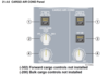
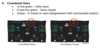
7. Forward Cargo Cold Air Valve
Displays the position of the forward cargo cold air valve. The valve is displayed:
- In-line green - Fully ________
- In-line amber - Failed ________
- Slant-line green - ________ open
- Slant-line amber - __ __________ or failed ________open
- Cross-line green - ________ closed
- Cross-line amber -________ closed
- Cross-line amber, and line indication also amber - At least one pack ________
V2 21.4.3
AIR_3
Discuss normal and abnormal indications on the ECAM COND page.
7. Forward Cargo Cold Air Valve
Displays the position of the forward cargo cold air valve. The valve is displayed:
- In-line green - Fully open
- In-line amber - Failed open
- Slant-line green - Partially open
- Slant-line amber - In transit or failed partially open
- Cross-line green - Fully closed
- Cross-line amber - Failed closed
- Cross-line amber, and line indication also amber - At least one pack off
V2 21.4.3