Op-amp technicalities Flashcards
(35 cards)
What are the limits of op-amps? (5 limits, 1 outcome)
> Output voltage cannot exceed the supply voltages
> Input voltage cannot exceed the supply voltages
> Input voltage × Gain (G) cannot exceed supply voltages
> Differential input limit is the maximum difference between the V- and V+ inputs.
> The common-mode input voltage (the average between the two input voltages) cannot be too high.
> If limits are exceeded, the op-amp may start to draw significant current.
What makes a system unstable?
When the output is not entirely controlled
How does feedback impact a systems stability? What is the purpose of feedback?
> Feedback does not necessarily improve stability as an open-loop system is stable, but it is not very useful.
> Feedback allows us to control a system whilst maintaining stability.
When does instability occur?
> When the phase of the feedback sifts by π radians (180°).
What happens to the equations for the inverting and non-inverting amplifiers when instability occurs?
The denominators f both equations become 1 - AB.
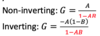
What are the 3 different cases of positive feedback signals?
> Small positive feedback: -1 < AB < 0
> Unstable system: AB = -1
> Large positive feedback: AB < -1
What happens when there is small positive feedback?
- 1 + AB < 1 - G > A
- The system is not strictly unstable but it is approaching instability.
- The gain is increasing rapidly.
- G ⇒ ∞
What happens when there is positive feedback and the system is unstable?
- 1 + AB = 0
- The equation becomes undefined (Does not apply anymore)
- Output is either at saturation at one of the supply voltages or has a self-sustaining oscillation
What happens when there is large positive feedback?
> It would appear that the system would become stable again with a negative output, but this does not occur.
> Gain equations are no longer valid in the region beyond where G ⇒ ∞
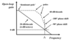
How does instability occur?
> Due to the design of an op-amp, there are several low pass filter stages in series
> Each low-pass stage produces an amplitude roll-off of 20dB/decade and a phase shift of -45° to 90° (at higher frequencies).
> Because they are in series, each phase shift acts on the preceding one.
> Eventually the phase shifts enough to cause positive feedback
What is the solution that op-amps use to prevent instability?
> We use a low-pass filter which reduces at a relatively low frequency such that it dominates the frequency response.
> We force the open-loop gain to reduce to unity well before the phase shifts can accumulate to a critical -180°
> This is called dominant-pole frequency compensation
What are the properties of the low pass dominant-pole frequency filter?
Roll off:
> 20dB/decade
> 6dB/ octave
> If we halve the signal frequency, then we will have twice as much open-loop gain Graph aspects:
> fT = The point where the gain is unity
> GBP: Gain bandwidth product GBP = fT
> GBW: Gain bandwidth GBW = fT Gain constraint:
> The closed-loop gain (G) cannot exceed the open-loop gain (A) and so the closed-loop is bounded by the open-loop. If the gain that we want is greater than the open-loop gain then we have a gain error.
What is phase margin?
> This is the difference between the total phase shift at fT and the critical -180° phase shift.
> This is a measure of how close the op-amp is to instability at the transition frequency
> We need to ensure that we do not introduce any additional phase shifts externally to the op-amp
Explain the different types of op-amp compensations
Fully compensated op-amp:
> The open-loop gain is rolled off to unity at a frequency where the phase shift is well below -180°
> This is done internally of the op-amp
Uncompensated op-amp:
> There is no in-built dominant-pole compensation
> The user is expected to add their own externally
Undercompensated op-amp:
> When the phase shift is at -180° the gain has not quite been rolled off to unity
> Intended to operate with a closed loop gain of 10 or more for high frequency circuits
> They are often called fast op-amps
> They are not stable at all
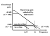
How do you calculate the gain error?
- Calculate the resistor configuration that will obtain the closed-loop gain that you wish to have
- Calculate the value of B for that configuration
- Decide what frequency you wish the op-amp to operate at
- Use the response graph to calculate the open-loop gain (A) at that frequency
- Insert the value of A and B into the gain equation for that type of op-amp and see what the actual gain becomes
How can inverting and non-inverting op-amps produce a gain that is less than unity/
> By using gain error to their advantage
> this method is not recommended
What can be said about the useful bandwidths of inverting and non-inverting amplifiers?
The useful bandwidth of the inverting configuration is only half that of the non-inverting configuration.
What happens when you require a unity gain that is close to fT?
> You need to include the imaginary aspect of phase shifting
Non-inverting: G = -j / (1 + (-j × 1)) = -j / (1 - j)) G ≈ 1/√2
Inverting: G = -j0.5 / (1 - 0.5j) ≈ 0.45
> If the open-loop gain is large (you are not near fT) then this does not matter
Describe what can be said about choosing an op-amp based off fT?
> It is poor practice to design an op-amp circuit for operation close the fT
> We also do not want to choose an op-amp with an excessively high fT
> 20dB gain can be ensured for: freq < 0.1fT
What is the issue with capacitive loads on op-amp circuits?
> Any load impedance which presents a capacitance between the output and ground introduces further phase shifting to the feedback path
What is the definition of slew rate?
The limit for the rate of change of output voltage with time.
Why will there be a limit to the slew rate?
Slew rate is limited by the finite internal current flow. An op-amp with a higher slew rate will draw more current from the power supply.
How is the maximum slew rate requred calculated? What are its units?
Max slew rate = Aω
Differentiating the input signal: V = Asin(ωt) ⇒ dV/dt = Aωcos(ωt)
Units: V/s
What is the problem if the slew rate is too large?
An op-amp with a very high slew rate may exhibit overshoot due to the combination of a fast output response and small but non-zero feedback delay.
