Thermodynamic Processes Flashcards
(35 cards)
Explain the relationship between real and ideal processes.
All real processes are irreversible; they are not done infinitely slowly. For any given volume, there is no well-defined pressure and temperature, since the system is not always in equilibrium.
Real processes can be compared to ideal to see how well the process or system is designed or built.
Explain the shape of the temperature-entropy (T-s) diagram process line for a typical boiler.
Because feedwater is normally subcooled, point 1 begins in the compressed liquid region. For a non-superheated plant, the steam exits with a quality greater than ninety-nine percent, so the process line would end on the isotherm (isobar) in the wet vapor region before reaching the Saturated Vapor Line.

Solve problems applying the General Energy Equation to secondary processes.
KE1 + PE1 + P1V1 + U1 + Q = KE2 + PE2 +P2V2 +U2 + W
Q= H2 - H1
Describe nozzle processes.
Nozzles are used to change the energy of a working fluid from one form of energy to another. Depending on the type of nozzle, the kinetic energy of the fluid will increase or decrease. There are several types of nozzles that perform different functions.
Nozzle Equation:
KE2 - KE1 = Hin-Hout
Solve nozzle process problems, applying the General Energy Equation.
Nozzle Kinetic Energy to Enthalpy Equation:
KE2 - KE1 = Hin - Hout
Describe the functions of nozzles in flow restrictors.
One simple use is as a flow restriction. The venturi-type nozzle is located in the main steam piping. The purpose of this nozzle is to limit the flow of steam to the atmosphere in the event of a downstream, main steam line (MSL) rupture. The nozzle serves as a flow restrictor by reducing the area available for the steam flow. During normal operation, this nozzle is sufficiently sized to permit normal steam flow rates.
Describe the functions of nozzles in air ejectors.
In the convergence of the first nozzle steam pressure falls and velocity increases, it passes through the throat with no change and exits the divergent zone into the suction box, here the steam velocity goes supersonic and pressure drops further which sucks non-condensable gases from the condenser. The steam and gases enter the convergent diffuser where pressure increases and velocity decreases. The combined flow exits the divergent divuser nozzle pressure increasing and velocity falling subsonic.
Describe the functions of nozzles in turbines.
In the turbine, the steam velocity is increased as it passes through a nozzle. This converts the steam thermal energy to kinetic energy by expanding the steam from a higher to a lower pressure.
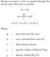
What is the Continuity Equation for steady flow processes?
What happens to steam pressure and velocity in a converging nozzle?
An increase in velocity in a converging nozzle is accompanied by a decrease in pressure. (area ↓, velocity ↑, and pressure ↓)
But under supersonic flow conditions: (area ↓, velocity ↓, and pressure ↑)
What happens to steam pressure and velocity in a diverging nozzle?
Velocity and kinetic energy decrease, and the pressure must have increase in a diverging nozzle. (area ↑, velocity ↓, and pressure ↑)
But in supersonic flow conditions: area ↑, velocity ↑, and pressure ↓
Describe the principals of operation of an air ejector.
Steam under pressure enters the convergent nozzle. The effect is expected (area ↓, velocity ↑, and pressure ↓).
As the sonic steam passes through the constant area of the throat of the nozzle, the velocity and pressure remain constant. At the exit of the throat, the area begins to increase. Here the velocity of the steam is dependent on the pressure downstream which is the same as the vacuum pressure in the main condenser. Flow velocity becomes supersonic. This effect is different from the expected responses of subsonic flow in a nozzle. Here the energy conversion does not follow expected subsonic responses (area ↑, velocity ↓, and pressure ↑) but instead the area ↑, velocity ↑, and pressure ↓.
The air and other gases are mechanically entrained with the high velocity steam. The high velocity steam molecules impinge the gas molecules, providing kinetic energy to the gas molecules. The energetic gas molecules travel with the steam out of the suction chamber and into the next convergent-divergent nozzle. This
reduces the number of molecules in the suction chamber area and allows other molecules from the condenser to be drawn into the suction chamber.
The pressure seen downstream of the convergent-divergent nozzle is now the off-gas system pressure. Off-gas system pressure is slightly higher than atmospheric pressure. To slow the supersonic flow before exiting the ejector, it is slowed by use of a convergent nozzle. Contrary to expected results in subsonic flow, as the supersonic steam enters the convergent nozzle, as the nozzle area decreases
the velocity of the steam and entrained molecules decrease and the pressure increases (area ↓, velocity ↓, and pressure ↑). Again this is opposite of expected results in subsonic flow conditions.
As the mixture flows through the constant area of the throat the velocity becomes sonic. The steam then enters the throat at sonic speed. The velocity and pressure remain constant through the throat. The steam mixture enters the final divergent
nozzle (also known as the subsonic diffuser). As the area of the nozzle increases, the velocity of the steam decreases to subsonic speeds and the pressure increases to the pressure of the off gas system. This energy conversion is as expected (area ↑, velocity ↓, and pressure ↑).
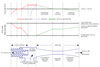
Draw the SJAE and Pressure/Velocity Changes through the system.
What are the two types of turbines?
impulse turbines and reaction turbines.
Impulse turbines require high velocity steam for efficient operation.
Reaction turbines are more efficient when using a lower velocity steam.
Explain the function of nozzles, fixed blading and moving blading in the turbine.
The convergent nozzles in the turbine casing accelerate and direct the steam into the blades, causing them to move. Impulse turbines have dished blades or buckets.
When more than one set of moving blades follows, fixed impulse blades are located between the moving blades to redirect the steam.
Explain the reason turbines are multi-staged.
Staging and compounding of impulse turbines are methods of removing a greater fraction of the energy stored in the inlet steam.
What is a pressure compounded turbine?
A pressure compounded turbine can extract energy by successive pressure drops. Since pressure decreases occur only through nozzles, a pressure compounded
turbine must consist of two or more stages.

What is a velocity compounded turbine?
A velocity compunded turbine can extract energy by successive velocity decreases, A velocity-compounded turbine may consist of only one stage: a nozzle followed by a set of moving blades, a set of fixed blades, and another set of moving blades.

Distinguish between actual turbine performance and ideal thermal efficiency, using a temperature-entropy (T-s) diagram.
The solid line, from point 1 to point 2, corresponds to the ideal process in which steam is isentropically expanded through the turbine rotors. The dashed line, from point 1 to point 2’, corresponds to the real irreversible process. Shown is the actual exhaust enthalpy of the steam where Point 2’ is greater than the ideal exhaust enthalpy, point 2. This demonstrates that the work output of a real turbine is less than that of an ideal turbine.

Distinguish between actual turbine performance and ideal thermal efficiency, using an enthalpy-entropy (h-s) diagram.
The solid line, from point 1 to point 2, corresponds to the ideal process in which steam is isentropically expanded through the turbine rotors. The dashed line, from point 1 to point 2’, corresponds to the real irreversible process. Shown is the actual exhaust enthalpy of the steam where Point 2’ is greater than the ideal exhaust enthalpy, point 2. This demonstrates that the work output of a real turbine is less than that of an ideal turbine.

What is turbine efficiency and what is the formula?
Turbine efficiency (ηt) is the ratio of work done by a real turbine to the work done by an ideal turbine in accomplishing the same gas expansion.

What is the general energy equation for a pump?
The General Energy Equation for a pump can be reduced to:
P1V1 + U1 = P2V2 + U2 + W
The equation can be further simplified by combining terms into enthalpy and dividing
through by mass to make the equation:
W = Hin - Hout
To obtain the total rate of work, multiply both sides by the mass flow rate, but leave the enthalpy terms as specific by not multiplying through yet.
Wp= M(Hin - Hout)
Distinguish between ideal and real pumping processes
on an enthalpy-entropy (h-s) diagram.
The solid lines (point 1 to point 2) represent the ideal isentropic pumping process, and the dashed lines (point 1 to point 2′) represent the real irreversible process.


