SYMBOLS Flashcards
(155 cards)
1. The primary element of any welding symbol is referred to as the:
- Tail
- Arrow
- Reference line
- Arrow side
- Weld symbol
1. The primary element of any welding symbol is referred to as the:
c. Reference line
2. Information appearing above the reference line refers to the:
- Near side
- Arrow side
- Far side
- Other side
- None of the above
2. Information appearing above the reference line refers to the:
d. Other side
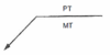
3. The graphic description of the type of weld is called the:
- Tail
- Welding symbol
- Weld symbol
- Arrow
- None of the above
3. The graphic description of the type of weld is called the:
c. Weld symbol
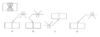
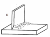
4. Which of the symbols below describe the weld shown?
a.
b.
c.
d.
e. None of the above

4. Which of the symbols below describe the weld shown?
a.

5. When a weld symbol is centered on the reference line, this indicates:
a. That the welder can put the weld on either side
b. That there is no side significance
c. That the designer doesn’t know where the weld should go
d. That the welder should weld in whatever position the weld is in
e. None of the above
- *5. When a weld symbol is centered on the reference line, this indicates:**
b. That there is no side significance
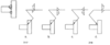
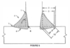
6. The symbol below depicts what type of weld?
a. Flare-V-Groove
b. Flare-Bevel-Groove
c. Edge-Flange
d. Corner-Flange
e. None of the above
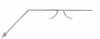
6. The symbol below depicts what type of weld?
a. Flare-V-Groove

7. In the symbol below, the 1/8 dimension refers to what?
a. Groove angle
b. Root face
c. Depth of preparation
d. Weld size
e. Root opening

- *7. In the symbol below, the 1/8 dimension refers to what?**
e. Root opening
8. In the symbol below, the ¾ dimension refers to what?
a. Weld size
b. Effective throat
c. Depth of bevel
d. Root opening
e. None of the above

8. In the symbol below, the ¾ dimension refers to what?
c. Depth of bevel

9. If applied to a 1-inch thick weld joint, the symbol below describes what type of weld?
a. Full penetration double bevel groove weld
b. Full penetration double V groove weld
c. Partial penetration double bevel groove weld
d. Partial penetration double V groove weld
e. None of the above

9. If applied to a 1-inch thick weld joint, the symbol below describes what type of weld?
a. Full penetration double bevel groove weld

10. Dimensions appearing to the immediate left of the weld symbol generally refer to the:
a. Weld length
b. Weld size
c. Root opening
d. Depth of preparation
e. None of the above
10. Dimensions appearing to the immediate left of the weld symbol generally refer to the:
b. Weld size
11. A triangular-shaped weld symbol represents what type of weld?
a. Bevel-groove
b. Flare-groove
c. Flange-groove
d. V-groove
e. None of the above
11. A triangular-shaped weld symbol represents what type of weld?
e. None of the above
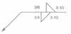
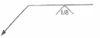
12. The symbol below described what type of weld?
a. Staggered intermittent fillet weld
b. Chain intermittent fillet weld
c. Segmented fillet weld
d. Intermittent fillet weld
e. None of the above

12. The symbol below described what type of weld?
b. Chain intermittent fillet weld
13. Dimensions appearing to the right of the plug weld symbol generally refer to the:
a. Weld size
b. Root opening
c. Weld length
d. Pitch distance
e. None of the above
13. Dimensions appearing to the right of the plug weld symbol generally refer to the:
d. Pitch distance
14. The type of weld symbolized by a rectangular box containing a dimension is best described as a:
a. Plug weld
b. Slot weld
c. Plug weld in beveled hole
d. Partially filled plug weld
e. Plug weld in hole having size shown
14. The type of weld symbolized by a rectangular box containing a dimension is best described as a:
d. Partially filled plug weld
15. The required spot weld size can be shown as the:
a. Dimension to the right of the symbol
b. Dimension of the required spot diameter
c. Value for the required shear strength
d. “a” and “b” above
e. “b” and “c” above
15. The required spot weld size can be shown as the:
E. “b” and “c” above
b. Dimension of the required spot diameter
c. Value for the required shear strength
16. A number appearing to the right of the spot weld symbol refers to:
a. Spot weld size
b. Spot weld length
c. Number of spots required
d. Pitch distance between adjacent spots
e. None of the above
- *16. A number appearing to the right of the spot weld symbol refers to:**
d. Pitch distance between adjacent spots
17. In the symbol below, the “5/8” dimension describes:
a. Weld size
b. Flange radius
c. Flange length
d. Depth of penetration
e. None of the above

17. In the symbol below, the “5/8” dimension describes:
a. Weld size

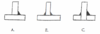
18. In the symbol below, the symbol shown on the other side represents:
a. Back weld
b. Backing weld
c. Melt-thru weld
d. “a” and “b” above
e. “b” and “c’’ above

- *18. In the symbol below, the symbol shown on the other side represents:**
c. Melt-thru weld

19. The symbol below shows the use of what type of weld?
a. Single-bevel-groove weld
b. Single-V-groove weld
c. Backing weld
d. Back weld
e. “b” and “c” above
19. The symbol below shows the use of what type of weld?
E. “b” and “c” above
b. Single-V-groove weld
c. Backing weld

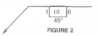
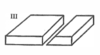
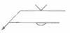
20. The symbol below shows what type of groove configuration?
a. Square groove
b. Skewed groove
c. Sloped groove
d. Scarf
e. None of the above

20. The symbol below shows what type of groove configuration?
d. Scarf

21. The part of the welding symbol which can be used to convey any additional information which cannot be shown otherwise is referred to as:
a. The weld symbol
b. The arrow
c. The reference line
d. The tail
e. None of the above
- *21. The part of the welding symbol which can be used to convey any additional information which cannot be shown otherwise is referred to as:**
d. The tail
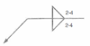
22. The symbol below shows what type of weld?
a. Gas metal arc spot weld
b. Resistance spot weld
c. Gas tungsten arc seam weld
d. Resistance seam weld
e. None of the above

- *22. The symbol below shows what type of weld?**
c. Gas tungsten arc seam weld

23. What nondestructive examination method is to be applied to the arrow side?
a. Magnetic particle testing
b. Eddy current testing
c. Radiographic testing
d. Penetrant testing
e. None of the above

- *23. What nondestructive examination method is to be applied to the arrow side?**
a. Magnetic particle testing
24. A number in parentheses just below/ above a test symbol describes:
a. The length of the weld to be tested
b. The extent of testing
c. The number of tests to perform
d. The type of test to perform
e. None of the above
- *24. A number in parentheses just below/ above a test symbol describes:**
c. The number of tests to perform