6. Electrical Flashcards
(25 cards)
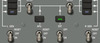
Recall ELEC SD symbology and color-coding

Power Buses
Green – Bus has normal power
Amber OFF – Bus does not have power

Recall ELEC SD symbology and color-coding

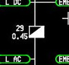
Battery
Green - Battery discharging normally
Amber - Battery voltage is less than normal OR battery discharge is abnormal. Voltage digits will be boxed and amber
White - No load on the battery. Load numerics are white in all conditions

Recall ELEC SD symbology and color-coding
Transformer Rectifiers
White – Normal ops
Amber – TR is failed

Recall ELEC SD symbology and color-coding
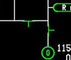
Generators
Green – Generator is on with voltage and frequency w/in limits
Amber – Generator tripped off. Voltage, frequency, and load current digits are boxed amber if not w/in limits
White – Engine is not operating OR generator is turned off. Voltage and frequency digits are white if within limits or engine is not operating. Load current digits are white if w/in limits

Recall ELEC SD symbology and color-coding

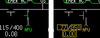
External Power
White – External power is available. EXT switch in OFF or main external power relay tripped
Green – External power on and supplying power
Blank – External power not connected

Recall ELEC SD symbology and color-coding
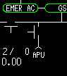
APU
White – APU power is available. APU generator off due to APU GEN switch in OFF or APU power relay tripped
Green – APU power on and supplying power
Amber – APU available. APU generator tripped off
Blank – APU power not available
Recall ELEC SD symbology and color-coding

Bus Tie Relay
Green – Relay is closed. Normal conditions
Amber – Relay tripped open
White – Relay is opened. Normal condition

Recall ELEC SD symbology and color-coding

Power Relays
Green – Relay is closed. Normal condition
Amber – Relay tripped open
White – Relay is opened. Normal condition

Recall ELEC SD symbology and color-coding

DC Tie Relay
Green – Relay is closed. Normal condition
Amber – Relay tripped open
White – Relay is opened. Normal condition

Recall ELEC SD symbology and color-coding
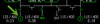
Schematic Flow Lines
White – Normal powered condition
Recall the function of the battery switch

OFF - connects to the battery direct bus only (battery charging not affected)
ON - Connects battery to the DC transfer bus and the battery direct bus
Recall the function of the EMER PWR Switch

OFF - Emergency power is off. Resets the automatic emergency power system
ARM – Supplies emergency power automatically when power loss to the EMER AC or DC bus is detected
ON - Emergency power is on. The battery supplies power for AC EMER bus (through the static inverter) and DC EMER bus
**Note: Emergency power can only be tested on the ground with both engines shut down. It is automatically tested when the switch is moved from OFF to ARM. During the test, the ON light illuminates and an EMER PWR TEST alert is displayed. A successful test is indicated when the ON light is extinguished and the alert is no longer displayed.
Recall which buses are powered on EMER PWR and how long the battery can provide power
When activated, the emergency power system will provide power to the following buses for approximately 60 minutes:
Battery direct bus
DC transfer bus
Emergency AC bus (through emergency inverter)
Emergency DC bus
Explain the function of the L/R BUS TIE Switches

Open – Respective generator cannot power the tie bus. Can also be used to reset a bus tie lockout on the ground
AUTO – Generator bus to tie bus connection is controlled automatically to meet aircraft power requirements
Recall the function of the DC BUS TIE Switch

OPEN - Opens all three DC bus tie relays
AUTO - DC bus tie relays are automatically controlled to ensure all DC buses are powered
Recall the function of the L/R GEN Switches

RESET – Resets the generator
OFF – Disconnects the generator from the respective bus
ON – Allows an operating generator to supply power to its respective bus
Recall the function of the APU Power Switch

RESET – Resets the generator
OFF – Disconnects the APU generator from the tie bus
ON – Allows an operating APU generator to supply power to the tie bus
Recall the function of the EXT Power Switch
OFF – Disconnects EXT PWR from the tie bus
ON – Connects EXT PWR to the tie bus
Recall the function of the GND SERVICE ELEC PWR Switch

OFF - Neutral position for ground service power
ON - Connects external power to the AC ground service bus and powers the DC ground service bus. EXT power switch is OFF
Recall the function of the GALLEY PWR Switch

OFF – Galley power is off
ON – Galley power is on
Recall features of the No Break Power Transfer (NBPT)
Normally, all electrical power source transfers will occur without power interruption
Momentary breaks in power supply, however, may occur during the transfer of power from the APU to an external source OR if a supplying generator experiences an unexpected power loss (due to a flameout or unexpected shutdown, etc)
Recall the amber, green and blue lights displayed on the ELECTRICAL panel

EMER PWR
ON – amber when EMER PWR is on
Recall the amber, green and blue lights displayed on the ELECTRICAL panel

APU PWR
ON – APU powering tie bus
Recall the amber, green and blue lights displayed on the ELECTRICAL panel

APU, L/R GEN, EXT PWR Lights
Blue – Indicate power source to associated bus

