CT - Chapter 6 Artifacts Flashcards
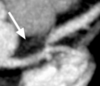
What is the arrow pointing at?

RV pacemaker leads - metal artifacts

What is one method of reducing image noise?
Increasing reconstructed slice thickness
- increases the amount of scintillation data used to construct each image –>
- image noise is reduced and overcome
What does the gantry rotation time define?
What artifacts does it affect?
- temporal resolution
- motion artifacts
- increasing rotation time –> reduces motion artifacts
How is tube current related to image noise?
increasing tube current –>
increases the photons per voxel –>
decreases image noise
How are image reconstruction kernels (filters) related to image noise?
smoother kernel/filter –> reduces image noise
sharper “edge-enhancing” kernels –> increase image noise
Describe the findings:

Beam Hardening Artifact
- occur when the photon beam is attenuated by a structure with especially high radiodensity (calcium, contrast, metal)
- A very low density hypoattenuated “streak” is seen adjacent to the high density structure

Describe the findings and diagnosis:
- 45 year old male with known CAD undergoes Cardiac CT to determine etiology of new onset cardiomyopathy
*

LV apical thrombus
- Important to distinguish this real finding from artifact, specifically beam hardening artifact (from mural calcium in this case)
- CT
- Batch reconstruction of sagittal sections through the LV
- LV apical thrombus which corresponds the the location of the patient’s wall motion abnormality (not shown)

Describe the findings:

Blood-contrast mixture
- SVC at the level of the insertion of the azygous vein
- serpiginous-appearing low-density within the SVC, and seeming to extend into the azygous, is not thrombus but the typical appearance of unopacified blood from one arm mixing with opacified blood from the other
- Common finding –> should not be mistaken for thombus

What artifacts typically degrade the quality of stent imaging?
- Beam Hardening artifacts
- Motion artifacts
- Partial volume artifacts
What is one artifact not typically associated with stent imaging?
Ring artifact
- seen when a detector is malfunctioning
What patient factor will always produce a non-diagnostic scan, and should always warrant pursuing an alternate testing modality?
inability to hold breath for the duration of the scan
- respiratory suspension is absolutely required during cardiac CT
- if a patient is unable or unwilling to hold their breath for the duration of the scan
- then the scan will be non-diagnostic and another testing modality should be used
Describe the findings related to reduced image quality:

Body habitus –> noise artifact
- example of excessive image noise –> renders coronary study non-diagnostic
- significantly increased “speckle” and noise within and surrounding each coronary image

Artifacts from dual chamber pacemaker leads MOST likely affect the image quality of the:
RCA
- one lead curls around in the RA and the second lead extends to the apex of the RV
Artifacts from Bi-V pacemaker leads MOST likely affect the image quality of the:
CFx
Describe the findings and most likely explanation for the discrepancy

The vessel line is incorrect
- such a stark discepancy between these orthogonal images should prompt a closer evaluation
- by examining the vessel line which is used to generate the curved MPR, one can see the vessel line is incorrect (travels outside of the contrast column)
- CT
- two images are orthogonal curved multiplanar reformats of the LAD and diagnoal branch
- Figure A - severe stenosis of proximal LAD
- Figure B - normal lumen caliber

Describe the findings:

Respiratory motion artifact
- coronary arteries are blurry and indistinct, indicating some kind of problem with the scan
- loss of detail is seen throughout the scan indicating most likely some kind of motion artifact
- Lung window:
- areas of streaking and “holes” (arrows) within the lung parenchyma adjacent to the contrast opacified vessels
- most consistent with motion of the lung parenchyma during the scan

Describe the findings:

Beam Hardening Artifact
- ventricular pacemaker lead that depicts two different artifacts:
- beam hardening
- motion
- due to high-density of metal skewing the energy profile of the incident photons
- error in reconstruction –> appears as very low-density (black) areas adjacent to the high density structure

Based on the comparative appearance of these two images, what element of the reconstruction was modified during the second reconstruction?
Slice Thickness
- Figure A is due to partial volume averaging –> the image has been reconstructed at a slice thickness of 5.0 mm, which is too thick for coronary imaging

Describe why slice thickness is so important in regards to coronary imaging
- Large slice thickness (typical thickness for non-coronary imaging) –> image depth is larger than the diameters of most of the coronary vessels –> other tissue and densities (perivascular tissue, epicardial fat) are incorporated into the image and averaged with the coronary arteries –> loss of distinction
- For coronary imaging, very thin sections ( < 1.0 mm) should be used in order to preserve distinct demarcation of the small coronary arteries
- this requires thin detector collimation as is typical for today’s multi-detector scanners
- but is not the case for 4-slice or older scanners
Describe the most likely finding:
- proximal (aortic) anastomosis of the SVG-LAD

Subtotal occlusion
- a bulky plaque is causing subtotal occlusion at the proximal anastomosis
- 80-year old male presented with acute chest pain at the ED, Troponin T was negative initially but spiked four hours later
- Angiography demonstrating subtotal occlusion

Define partial volume averaging
- occurs when adjacent structures with different CT-densities (calcium, endothelium) are averaged into one CT attenuation value of one voxel
- manifestation of the limited spatial resolution of CT
- adjacent, non-calcified structures are depicted as having an attenuation that is higher than actual, and this results in calcifications –> appear larger than they really are
- often influences ability to interpret CCTA
What is one way to minimize partial volume averaging?
sharp reconstruction kernal/filter
Describe the findings and best way to prevent this from occuring

Misalignment or Step artifacts (respiratory motion)
- clearly indicated by the step artifacts within the sternum
Ensure patient understands and follows the breath hold command

Describe the findings

Cardiac motion artifact due to ectopy
- EKG strip:
- two PVC’s during scan
- misgating of the rhythm (broken arrow) in which pat of the baseline was “tagged” as a QRS therefore adding a beat where none was present
- Incorporation of these beats will have disastrous consequences for the reconstruction
*****Usually not necessary to rescan patient –> EKG editing to correct for these arrhythmias and errors

Describe the findings

Streak or Metal Artifact

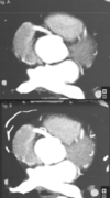
Describe the findings:

Slab Artifact
- sagittal plane image depicts a gradient of opacification within the RV, with decreasing contrast opacification in the cranial-to-caudal direction
- within this gradient, a series of “slabs” can be visualized, each demarcating a new zone of decreased opacification
- more caudal portions of the image are obtained later in the scan, when the contrast bolus has already passed through and then washed out of the RV

What are common causes of misalignment artifact?

- HR
- Arrhythmia during scanning
- Respiratory motion

Describe the findings

Normal myocardial perfusion; no infarct or ischemia
- hypodensities:
- subendocardial in inferosetpal wall
- intramyocardial inferolateral wall (more likely artifact based on location)
- Second reconstruction –> resolution of findings (likely secondary to cardiac motion)

Describe the findings on CTA and coronary angiogram

Volume Averaging - “Blooming” Artifact
- artifact occurs when the reconstruction process averages data from surrounding voxels to depict the dense calcifications
- calcified lesions will appear larger than they actually are
- can be ameliorated by specific reconstruction algorithms designed for calcium

Describe the findings

Venous inflow artifact (heterogeneous contrast density)
- due to persistent left SVC

Describe the findings

No stenosis; the 75% phase represents a false positive
- example of the manner in which reconstruction of the data using a timeframe in which cardiac motion was still occurring can distort the appearance of the coronary anatomy
- CT images:
- 75% R-R window = ostial LAD focal stenosis vs. 80% R-R window = no stenosis.
- Two clues to help distinguish the true representation of coronary anatomy:
- motion artifact present in 75% reconstruction
- unusual for a stenosis to be present but not have a visualized plaque in association with the stenosis
Describe the findings
What, if anything, should be done before the patient leaves?

Review the EKG obtained during the scan
- 3D volume rendered image –>
- misalignment artifact (arrow) cutting through the mid-upper right and left ventricles

Describe the findings

Insufficient volume of contrast
- Reconstructed double-oblique image plane oriented to display a two-chamber view of the LV
- contrast gradient within the left atrium and ventricle –> mirrors the decreasing concentration of contrast within those chambers as the scan is proceeding

Describe the problem with the current settings:
- Cardiac CT performed to evaluate chest pain using a 64-slice scanner in helical mode
- Scan time = 12 s
- Contrast load = 60 mL
- Flow rate 5 mL/s
- delivered by bolus tracking using an ROI in the thoracic aorta
- Post-threshold delay = 5 s

Contrast gradient in LA and LV - decreasing concentration of contrast
- Opacification of RV and LV starts out well, with bright opacification of the top of the LV, while the RV has already washed out but
- 12s scan time + 5 second post-threshold delay = 17 s total time contrast should run
- 17s x 5 mL/s flow rate = 85 mL total contrast volume
- Scan time is correct, but volume of contrast is inadequate
****patient had renal insufficiency –> attempts made to restrict contrast exposure

Describe the findings and explanation for differences of the CFx

The lumen is stenosed by focal non-calcified plaque, and the alternate image is a pitfall of interpretation produced by the use of maximim intensity projection
- CT findings:
- axial slice of mid-CFx
- pitfall that may be encountered in focal lesions in coronary segments that course perpendicular to the axial plane
- use of MIP may cover up such a lesion –>
- since contrast proximal and distal to the stenosis will be preferentially projected over the lesion and therefore obscure it
- Hightlights the importance:
- always examining these datasets initially with thin cuts (without a MIP)
- using multiple image planes (at least axial and coronal)
***Invasive angiography –> focal stenosis in mid-CFx

Describe the findings

Mixing / inflow artifact of SVC at azygos inflow site
- inflow phenomena cause hypodense artifacts especially in the subclavian vein and SVC
- saline chaser reduces inflow phenomena in:
- Subclavian
- SVC
- RV

Describe the findings

Beam Hardening Artifact
- often seen in the inferobasal segments of the LV
- they originate from the diaphragm tip (liver cuppula) and/or from the posterior descending aorta or spine
- mean CT attenuation of approximately 50 HU
- compared to approximately 90 HU in the normally opacified myocardium

Describe the findings and RCA stenosis

Motion artifact - RCA not assessable
- typical boomerang appearance of motion artifact in the RCA
- spot of very low attenuation inside the boomerang is also characteristic
***patient had HR = 92 bpm

What is the cause of this artifact?

Reconstructed slice thickness is too large
- significant stairstep artifact present throughout the image, most apparent along the lateral border of the LV and medial border of the RA
- Consistent stairstep artifact –> result of reconstructing axial images at a slice thickness that is inappropriately large –> loss of z-axis resolution –> becomes more apparent in non-axial planes, such as this coronal plane image

In the RCA image shown below, arrows 1 and 2 are pointing at which findings?

1 = Misalignment artifact
- due to variable heart rate during image acquisition
- shows as displacement of the artery along a longitudinal axis ( = stair “step”) through the entire image
2 = Motion artifact
- mid/distal RCA is often affected due to its highest intrinsic velocity
- presence of calcium further exacerbates the “blurred” appearance of the vessel and obscures the lumen

What is the artifact ( #2)?
How is it corrected for in the below image?

- Motion artifact
- adjusting the image reconstruction window
****Misalignment artifact (“stair” step) appearance remains in #1

Describe the findings (hypodensity in the basal inferior wall of LV):

Cardiac Motion Artifact - “Pseudoinfarct” pattern
- Multiple indicators of significant cardiac motion:
- irregular contour of the aortic root
- “double shadow” of the endocardial border of the anteroseptum
- Dome of diaphragm is artifact-free, indicating good breath hold and unlikely respiratory motion
- Lower image:
- reconstruction in a quiescent, motion-free window reveals normal myocardium

Describe the cardiac devices present which account for the metal artifacts shown

Biventricular pacemaker and mitral valve ring
- A - right atrial lead (curling up into the right atrial appendage)
- B - RV lead and the portion of the LV lead traveling through the RA
- C - mitral valve ring (but notice that leaflets or struts of a full mitral valve prosthesis are not present)
- D - portion of the LV lead in the coronary sinus as it makes its way toward the lateral wall of the LV

Describe the findings

- Cardiac motion artifact in a patient with dilated aortic root
- Prevent this artifact by:
- pay attention to ECG gating and cardiac rhythm
- all suspected ascending aortic dissection protocols should be performed following contrast administration, using ECG gating

Describe the findings:

Cardiac motion artifact
- typical cardiac motion artifact
- evidence of “steps” in the heart
- Can be due to multiple factors:
- inadequately controlled HR
- frequent ectopy
- irregular R-R interval

How can you differentiate respiratory and motion artifact?
- motion artifact
- “steps” in the heart but not on the ribs
- respiratory artifact
- “steps” present in the heart and in the ribs

Describe the findings:

”mixing” artifact
- commonly seen in the RA or RV due to incomplete mixing of contrast and blood
- can hamper the diagnostic capability of CT in the evaluation of right-sided structures

Describe the view and labels

Horizontal Long Axis
